State of the art
The free-carrier-properties effective mass m*, mobility m, and carrier concentration N are of fundamental importance for
understanding basic material properties of semiconductors. N, m*, and m intriguingly combine concepts of classical
(such as the effective "inertial" carrier mass) and quantum physics (e.g., the energy-momentum-dispersion and band
occupation). A long term goal has been the accurate and simultaneous measurement of N, m, and m* by non-contact optical
means in materials which are part of complex layered systems, such as semiconductor heterostructures.
Commonly, the electrical Hall-effect is measured to access N and m, which requires ohmic contacts. Such measurements
are difficult if the material of interest is part of a complex layer structure, eventually buried by other highly-resistive
or differently-conductive layers. The correct interpretation of the electrical measurement requires furthermore exact knowledge
of the contact geometry, because Schottky barrier formation or space charge accumulation potentially affect the results.
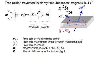
According to the Drude model, the dielectric function e provides access to the square of the free-carrier (unscreened) plasma frequency
wp and plasma resonance broadening gp. Under simplified assumptions about the free-carrier momentum distribution function
- a single-species-carrier-plasma taken as example - wp and gp translate into the coupled quantities N/m* and m*m. No
distinction can be made between N, m*, and m from measurement of e alone, nor can the sign of q be determined because wp
is proportional to |q|. However, when brought into a magnetic field, the Lorentz force renders e a complex tensor, and
provides the additional information required to obtain m* and sign(q). For semiconductor materials, this can be done by
measurement of the magnetic-field-induced free-carrier birefringence. This approach is also applicable to organic conducting
materials.
 Fig. 0.
|
|
Generalized Ellipsometry
Standard (isotropic) ellipsometry determines two independent parameters, which provide the dielectric function e
avoiding the Kramers-Kronig extension of pure intensity spectra in order to access both real and imaginary parts of e
. Generalized ellipsometry extends to arbitrarily anisotropic materials, and allows for determination of the complete e
tensor. Six parameters, which consist of the elements of the Jones reflection matrix, can be measured. The Jones matrix
depends on the sample structure, each sample constituent's e, the ambient index of refraction,
and the angle of incidence Fa. Treatment of anisotropic media is alternatively
done within the Mueller-matrix- and Stokes-vector-approach. The elements of e follow by
comparing calculated data to measured data upon standard least-square fit procedures. In addition to the ellipsometric
parameters their standard deviations are determined, and propagated into the uncertainties (standard error) of the
resulting fit parameters.
Far-infrared magneto-optic (MO) ellipsometer
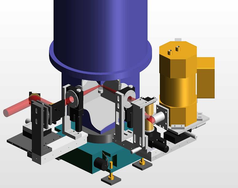
Our setup uses a superconducting magnetocryostat (Oxford) with optical access ports and temperature-controlled (4K - RT)
sample holder (Fig. 1.  Fig. 1.
The magnetocryostat is kindly provided by Professor Dr. Pablo Esquinazi.)
The magnetic field is parallel to the incident beam direction, and the angle of incidence is 45°. The strength of the
field can be varied between B = -6T ... 6T. The beam is guided through exterior and interior windows, made from
diamond and polyethylene. A third set of windows allows for transmission-type measurements. Details of a previous setup are given in
M. Schubert, T. Hofmann, C. M. Herzinger, J. Opt. Soc. Am. A 20, 347 - 356 (2003).
|

